O nas
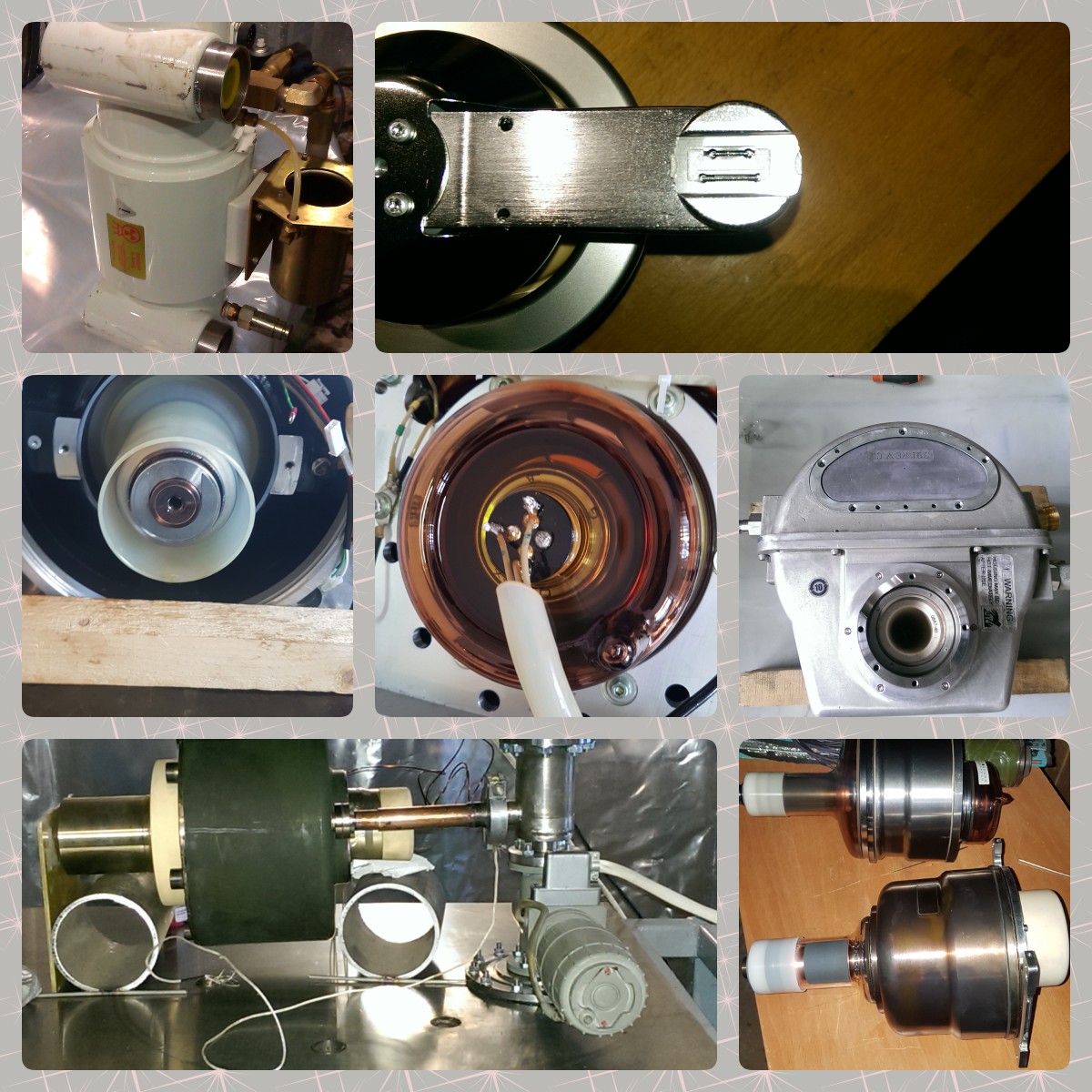
Od ponad 10 lat zajmujemy się naprawą lamp rentgenowskich CT.
W 2013 roku w bazie technologicznej Electropolyus LLC (Charkiw, Ukraina) rozpoczęto prace nad technologią naprawy lamp rentgenowskich do tomografów komputerowych. Naszym celem była wymiana żarników zespołu katody oraz przywrócenie próżni we wkładce.
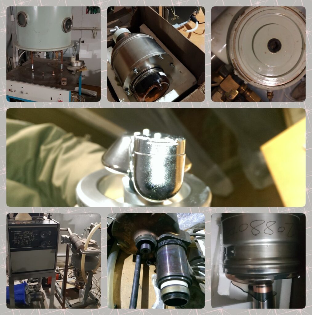
Po siedmiu latach pracy uzyskaliśmy stałą poprawę podciśnienia we wkładce, co umożliwiło uruchomienie lamp rentgenowskich różnych marek (MX200, DURA-202, DURA 532 AKRON Q). Niestety, po rozpoczęciu wojny na Ukrainie, podczas bombardowań zniszczeniu uległ główny sprzęt.
Obecnie w Polsce trwa proces przywracania niezbędnego sprzętu. W ostatnich latach pojawiły się inne kierunki w kwestii naprawy lamp rentgenowskich do tomografii komputerowej.
Stworzyliśmy urządzenie mające na celu eliminację spadku emisyjności lampy rentgenowskiej oraz zwiększenie poziomu podciśnienia we wkładce. Aktywnie rozwijane są również metody i małogabarytowe urządzenia do szybkiej diagnostyki lamp rentgenowskich instalowanych bezpośrednio na tomografie komputerowym. Taki sprzęt może być przydatny zarówno dla inżynierów obsługujących tomografy komputerowe, jak i dla inżynierów pracujących w magazynach sprzętu medycznego.
About Us
For more than 10 years, we have been engaged in the repair of CT X-ray tubes.
In 2013, the development of a technology for repairing X-ray tubes for computer tomographs began at the technological base of Electropolyus LLC (Kharkiv, Ukraine). Our specific goal was to replace the filaments of the cathode unit and restore the vacuum in the insert.
After seven years of work, we successfully established a stable improvement in the vacuum in the insert, allowing us to put into operation X-ray tubes of various brands, such as MX200, DURA-202, and DURA 532 AKRON Q. Unfortunately, after the war in Ukraine began, the main equipment was destroyed during the bombing.
Currently, the process of restoring the necessary equipment is underway in Poland. In recent years, new advancements have been made in the field of repairing X-ray tubes for CT.
We have developed a device to eliminate the drop in emissivity of the X-ray tube and increase the vacuum level in the insert. Additionally, methods and compact equipment for the rapid diagnostics of X-ray tubes installed directly on CT scanners are being actively developed. This equipment can be valuable both for engineers servicing computer tomographs and for those working in medical equipment warehouses.
TUBE FOR SALE
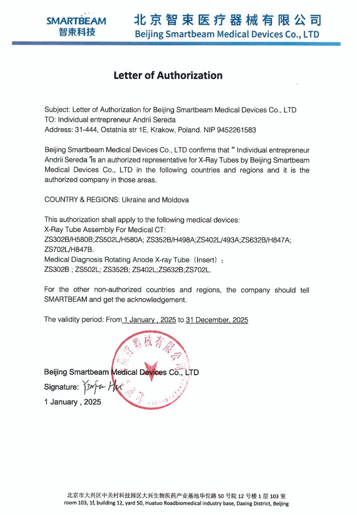
Mam zaszczyt zaoferować doskonałe lampy rentgenowskie do tomografii komputerowej produkcji Zhuhai RCAN Medical Equipment Co., Ltd Chiny. Świetnie sprawdziły się na różnych tomografach komputerowych w różnych krajach.
I am honored to offer excellent X-ray tubes for CT manufactured by Zhuhai RCAN Medical Equipment Co., Ltd, China. They have proven themselves well on various CT scanners in different countries.

RH406
RH526
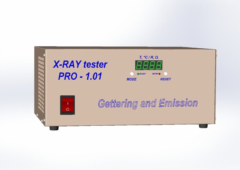
Urządzenie do sprawdzania i odnawiania lamp rentgenowskich
Device for checking and restoring X-ray tubes
Głównym celem urządzeń przedstawionych w tej sekcji jest pomoc inżynierom w prawidłowej diagnostyce systemów CT. Określenie przyczyny awarii w układzie zasilania systemu rentgenowskiego CT nie zawsze jest łatwe i jednoznaczne. Przyczyną może być generator, zbiornik wysokiego napięcia, lampa lub złącza i przewody. Najdroższym elementem w tym łańcuchu jest lampa.
Oferowane urządzenia znacznie uproszczą testowanie lampy bezpośrednio na tomografie, bez demontażu. Będą również przydatne dla inżynierów pracujących w magazynach sprzętu medycznego do sprawdzania sprawności przechowywanych lamp. Dodatkowo urządzenie ‘getter i emission’ przedłuży żywotność lampy w przypadku wystąpienia przebić (arcs, spits) wewnątrz wkładki lub spadku zdolności emisyjnych żarników.
The main purpose of the devices presented in this section is to help engineers accurately diagnose CT systems. Determining the cause of a malfunction in the power circuit of a CT X-ray system is not always simple and straightforward. The cause could be the generator, high-voltage tank, tube, or connectors and wires. The most expensive element in this chain is the tube.
The offered devices will significantly simplify the testing of the tube directly on the CT, without disassembly. They will also be useful for engineers working in medical equipment warehouses to check the operability of stored tubes. Additionally, the ‘gettering and emission’ device will extend the life of the tube when breakdowns (arcs, spits) occur inside the insert or when the emission capacity of the filaments decreases.
Sprzęt w fazie rozwoju
Equipment in development phase
Usługi naprawy lamp rentgenowskich
X-ray tube repair services
Lampy rentgenowskie starzeją się. Ich żywotność jest ograniczona, ponieważ ich charakterystyki stopniowo się pogarszają, a zużyte materiały ulegają wyczerpaniu. W związku z tym efektywność pracy lamp spada aż do całkowitego zatrzymania.
Każda lampa rentgenowska składa się z metalowej obudowy, elementów wewnętrznych (system magnetyczny z uzwojeniem do napędu anody, przekaźnika ciśnienia, przekaźnika temperatury, izolatorów, przewodów itp.), inserta, oraz zazwyczaj ciekłego dielektryka (oleju izolacyjnego).
Podczas pracy lampy jej elementy są narażone na cykliczne nagrzewanie. Zespół katodowy nagrzewa się do 450 stopni Celsjusza, a anoda podczas pracy lampy nagrzewa się do 1100 stopni Celsjusza. Olej izolacyjny, oprócz izolacji, musi zapewniać wystarczające chłodzenie inserta. To prowadzi do zmiany struktury oleju. Olej ulega spalaniu w kontakcie z rozgrzanymi częściami wkładki i po pewnym czasie przestaje pełnić funkcję izolatora.
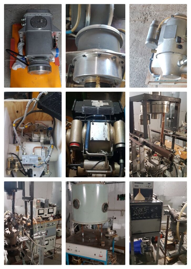
X-ray tubes age. Their lifespan is limited as their characteristics gradually decline, and the materials used are consumed. Therefore, the efficiency of the tubes decreases until they completely stop working.
Every X-ray tube consists of a metallic body, internal elements (magnetic system with a winding for anode drive, pressure relay, temperature relay, insulators, wires, etc.), an insert, and usually a liquid dielectric (insulating oil).
During the operation of the tube, its elements are subjected to cyclic heating. The cathode assembly heats up to 450 degrees Celsius, and the anode, during the operation of the tube, heats up to 1100 degrees Celsius. The insulating oil, in addition to insulation, must provide sufficient cooling for the insert. This leads to changes in the structure of the oil. It burns when in contact with the heated parts of the insert and eventually ceases to function as an insulator.
Uszczelki metalowo-szklane i metalowe połączenia lutowane inserta podlegają zmęczeniom i po pewnym czasie zaczynają przepuszczać niewielkie ilości gazu, stopniowo zwiększając ciśnienie gazu. Ponadto podczas pracy lampy mogą się uwalniać resztki gazów rozpuszczonych w materiałach wewnętrznych osprzętu wkładki. Obie te przyczyny prowadzą do pogorszenia próżni we wkładce. Efektywność pracy lampy zaczyna spadać i w konsekwencji dochodzi do wysokiego napięcia łukowego, które może być spowodowane zwiększonym ciśnieniem gazu we wkładce.
Większość lamp jest wykonana z szklanymi bańkami jako izolatorami dla elektrod lampy (katody, anody i centralnego korpusu), aby zapobiec prądom upływowym i wyładowaniom łukowym. Z upływem czasu i w zależności od współczynnika użytkowania metal anody i włókna żarzenia zaczyna parować i osiadać na wewnętrznych szklanych powierzchniach inserta, co w przyszłości powoduje wyładowania łukowe i uszkodzenie lampy.
Przebicie łukowe jest problemem typowym dla wszystkich systemów wysokiego napięcia. Oprócz wspomnianych wcześniej przyczyn, wysoki poziom gazu w próżni, parowanie przewodzącego metalu z osadzaniem się na powierzchniach izolatorów oraz powstawanie pęknięć izolatorów mogą prowadzić do zwiększonego ciśnienia gazów lub zmniejszenia zdolności izolatorów do wytrzymywania wysokiego napięcia.
Każda przyczyna awarii lampy ma swoje oznaki. Lampy bardzo rzadko psują się nagle. Przy regularnym serwisowaniu i uważnym analizowaniu dziennika błędów można dostrzec oznaki zbliżającej się awarii lampy. Może to dać możliwość przedłużenia żywotności lampy i przygotowania się do zakupu nowej bez przestojów tomografu.
Propozycja naprawy lamp rentgenowskich do tomografii komputerowej polega na tym, że na pewnym etapie życia lampy należy przeprowadzać:
– wymianę oleju izolacyjnego i płynu chłodzącego (jeśli przewidziane jest chłodzenie dwukanałowe);
– czyszczenie wewnętrznych powierzchni obudowy i wewnętrznych izolatorów lampy oraz zewnętrznych powierzchni wkładki;
– poprawę próżni we inserte;
– przywrócenie zdolności emisyjnych katod.
Wszystkie te operacje mogą być wykonywane w laboratorium.
The metal-glass seals and metal soldered joints of the insert undergo fatigue stress and eventually start to leak small amounts of gas, gradually increasing gas pressure. In addition, during the operation of the tube, residual gases dissolved in the materials of the internal fittings of the insert may emerge. Both these reasons lead to a deterioration of the vacuum in the insert.
The efficiency of the tube begins to decline, and as a result, high-voltage arc discharges occur, which can be caused by increased gas pressure in the insert.
Most tubes are made with glass envelopes as insulators for the tube electrodes (cathode, anode, and central body) to prevent leakage currents and arc discharges. Over time and depending on the usage coefficient, the metal of the anode and filament begins to evaporate and deposit on the internal glass surfaces of the insert, which eventually causes arc discharge and tube failure.
Arc discharge is a problem typical for all high-voltage systems. In addition to the reasons mentioned above, a high level of gas in the vacuum, the evaporation of conductive metal with deposition on the surfaces of insulators, and the formation of cracks in insulators can lead to increased gas pressure or reduce the ability of insulators to withstand high voltage.
Each cause of tube failure has its precursors. Tubes very rarely fail suddenly. With regular maintenance and careful study of error logs, one can see the precursors of tube failure. This can provide an opportunity to extend the life of the tube and prepare for the purchase of a new one without CT downtime.
The proposal for repairing X-ray tubes for CT involves performing the following at a certain stage of the tube’s life:
– replacing the insulating oil and coolant (if dual-circuit cooling is provided);
– cleaning the internal surfaces of the body and internal insulators of the tube, as well as the external surfaces of the insert;
– improving the vacuum in the insert;
– restoring the emission capacity of the cathodes.
All these operations can be performed in a laboratory.
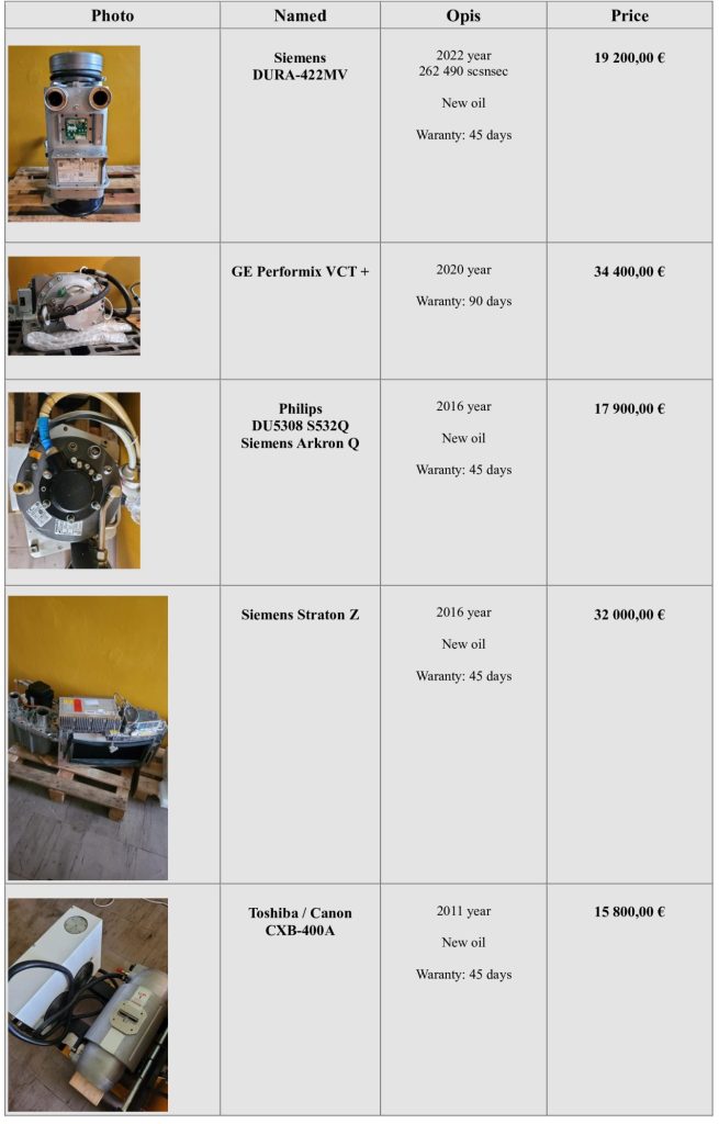
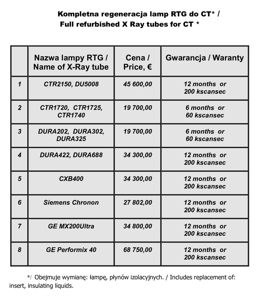
CENA / PRICE
Kontakty
Contacts
30-740, ul. Połłanki 80
Kraków, Polska
+48784462822
info@xraytesterpro.com